Easy Nextion Library Custom Protocol Explained
Introduction

At page Use Nextion : General View we described what types of data Nextion can send.
The next step is that we must have a way to read them, over the Serial, and then assign them to functions or variables. This is where the custom protocol comes in clutch., giving the abillity to to organise the commands that are going to be used with the simplest method possible, idenifying them with the Arduino code and assigning them to the commands we want.
All these are already built-in and all you have to do is to classify your needs.
An example on how to sort a group of commands follows and we take as an instance a very commonly used and necessary task for turning ON/OFF some relays
Contents:

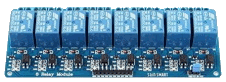
Example for ON/OFF Relays

Now let’s see how we can assign commands to turn ON/OFF some relays.
Build the protocol **For more details on how it is built, see docs after the example**
value <0>
Relay's ID on MCU. In HEX = 00
value <1>
Relay's ID on MCU. In HEX = 01
etc.
printh 23 02 52 01 for Relay 1
To assign the commands to the proper tasks at MCU side, first we must read them
We read the commands with the NextionListen() function.
We don’t have to change or add anything in this function.
As the code is enough commented already, only a few words are enough.
• We read the Serial continually
• When the start marker <#> is identified we wait for number of bytes that we have specify with the <len> parameter.
• When we have all the expected bytes on Serial, we are sure that we found a command.
• We read and store the next byte that according to our protocol is the task ID or the command croup.
Second part is the assing of the commands
For that we call the readCommand() function and with a switch() command we assing them to tasks.
The readCommand() function is placed on the file readCustomCommands.cpp .
It is the only function on this file and we separate it from the main code in order to have easy access and simplicity for the modification and also to avoid mistakes and errors on the rest of library’s code.
readCustomCommands.cpp is the only file that we have to modify and add cases upon our needs.
Two cases is already predefined for future use.
Here is the code for the readcommand() function as an example on how we assign pages:
switch(_cmd1){  // _cmd is the variable where previous we have store the command ID
  case 'P':     /*or <case 0x50:>  If 'P' matches, we have the command group "Page".
                 *The next byte is the page <Id> according to our protocol.
                 */
                // We set value of the clobal variable currentPageId egual to the reading byte.
    currentPageId = _serial->read();
    // break to Leave the case.
    break;
}
Step 1:
Prepare the Arduino code
On Arduino’s code we declare the pins for every Relay in an array:
const uint8_t TOTAL_RELAY = 6    // How many warning relays we use


const uint8_t relayPin[TOTAL_RELAY] = {2, 3, 4, 5, 6, 7};  // assigns the pin number for every relay
 /*
  * Declare that pin D2 is the pin that controls the Relay No0 (front lights)
  * Declare that pin D3 is the pin that controls the Relay No1 (Backyard lights)
  * Declare that pin D4 is the pin that controls the Relay No2 (swimming pool lights)
  * Declare that pin D5 is the pin that controls the Relay No3 (roofgarden lights)
  * Declare that pin D6 is the pin that controls the Relay No4 (adviser lights)
  * Declare that pin D7 is the pin that controls the Relay No5 (extra auxiliary lights)
  */
With a for() loop, setup the pins in the setup() function
 void setup(){
  // initialize relay outputs
  for(int i = 0; i < TOTAL_RELAY; i++){
    pinMode(relayPin[i], OUTPUT);     // Setting relay pin as OUTPUT
    digitalWrite(relayPin[i], LOW);  //Setting relay to LOW (off)
  }
}
Step 2:
Prepare the buttons on Nextion
Fron Nextion editor greate the buttons you need and on the Touhgt Release Event write the command:
printh 23 02 52 00 for the Relay No 0. printh 23 02 52 01 for Relay No1. For the Relay No 10, remember the HEX printh 23 02 52 0A
Step 3:
Modify the readCommand() function
Open the file readCustomCommands.cpp from the library's folder.
Go under the predefined case for future use and modify the code, like this:
 case 'R':  // or case 0x52:  If 'R' matches, we have the command group "Relays".
           // from the event of the button: < printh 23 02 52 xx > where xx the relay ID
  _tempRead = _serial->read(); // Read and Store the next byte to a local variable _tempRead

  digitalWrite(relayPin[_tempRead], !digitalRead(relayPin[_tempRead]));

  break;
The variable _tempRead must be created from the user.
Declare the variable outside the cases and the switch() command.
Prefer to create the variable above the switch() :
 void EasyNex::readCommand(){

  int _tempRead;

  switch(_cmd1){
    case 'P':
//...code continues
That’s all. Now every time a button is pressed, changes the stage off the assigned Relay from ON to OFF and the opposite.
Now, the full code:
//------------------------------------------------------------------------
//______________________ EasyNextionLibrary Configuration
//------------------------------------------------------------------------
#include "EasyNextionLibrary.h"

EasyNex myNex(Serial); // Create an object of EasyNex class with the name < myNex >
                       // Set as parameter the Serial you are going to use
//------------------------------------------------------------------------
//______________________ Relays Configuration
//------------------------------------------------------------------------

const uint8_t TOTAL_RELAY = 6    // How many warning relays we use


const uint8_t RelayPin[TOTAL_RELAY] = {2, 3, 4, 5, 6, 7};  // assigns the pin number for every relay
 /*
  * Declare that pin D2 is the pin that controls the Relay No0 (front lights)
  * Declare that pin D3 is the pin that controls the Relay No1 (Backyard lights)
  * Declare that pin D4 is the pin that controls the Relay No2 (swimming pool lights)
  * Declare that pin D5 is the pin that controls the Relay No3 (roofgarden lights)
  * Declare that pin D6 is the pin that controls the Relay No4 (adviser lights)
  * Declare that pin D7 is the pin that controls the Relay No5 (extra auxiliary lights)
  */

void setup(){
  // initialize relay outputs
  for(int i = 0; i < TOTAL_RELAY; i++){
    pinMode(relayPin[i], OUTPUT);     // Setting relay pin as OUTPUT
    digitalWrite(relayPin[i], LOW);  //Setting relay to LOW (off)
  }

  // Initialize EasynextionLibrary
  myNex.begin(9600); // Begin the object with a baud rate of 9600
                     // If no parameter was given in the begin(), the default baud rate of 9600 will be used
}

void loop(){

  myNex.NextionListen(); // This function must be called repeatedly to response touch events
                         // from Nextion touch panel. Actually, you should place it in your loop function.

}
//*******************************************************************************************
// AND THIS MUST BE ADDED INSIDE THE switch() , replacing the 'X' future use case
// In the readCustomCommands.cpp file in library's  src  folder
//*******************************************************************************************
/*
 case 'R':  // or case 0x52:  If 'R' matches, we have the command group "Relays".
           // from the event of the button: < printh 23 02 52 xx > where xx the relay ID
  _tempRead = _serial->read(); // Read and Store the next byte to a local variable _tempRead

  digitalWrite(relayPin[_tempRead], !digitalRead(relayPin[_tempRead]));

  break;
*/
//*******************************************************************************************
// The variable _tempRead must be created from the user.
// Declare the variable outside the cases and the switch() command.
// Prefer to create the variable above the switch()
//*******************************************************************************************
The custom protocol in detail
The powerful tool of the User-code Event:
Nextion has a white section under the Touch Events of any component, in which you can write commands or data, that can be sent by Serial using the three print commands set.
You could even write a whole code in there, by using if, for or while statements. On the condition that it is going to be executed on Nextion.
In addition, Nextion’s MCU has faster clock speed, of 48MHz on Basic, 108MHz on Enhanced over 3.5” and 200MHz on Intelligent, whereas the Arduino’s Nano and UNO have a clock speed of 16MHz.
Thus, we should prefer to perform most of the tasks on Nextion rather than Arduino, with the power tool of User-code Event.
What is a protocol?
Protocols are based on specific rules, guidelines and regulations for computing and are designed for efficiency.
Each rule is defined in different terms and is assigned a unique name.
Simple words: A protocol is a set of rules to follow.
Let’s make these rules:
We agree that a command is consist of several bytes and each one of them contains a data type.
That the First of the bytes is the start command marker that declares that a command is followed and as start marker we choose the <#>.
With the second of the bytes we specify the length of the command, which means the number of bytes that will follow and we name it <len>.
With the third of the bytes we specify the task that the command is intended to, and we named <cmd>.
All the followed bytes are going to be used to specify the parameters and the properties that we need for the task,
one byte for each parameter and for as many bytes are required. Name them <id>
After those rules, our commands will have this format:
<#>
<len>
<cmd>
<id>
<id2>
- <#> declares that a command is followed
- <len> declares the number of bytes that will follow
- <cmd> declares the task of the command
- <id> declares the properties of the command
- <id2> a second property of the command
We can use as many property IDs as we want
The only thing that remains to do, is to organize the commands that we are going to use with the simplest possible method.
The most common tasks that needed on a project and they are already build in to the Easy Nextion Library are the following:
Page that is loaded, and trigger Function.
We are going to explain them:
Here is how to organize those tasks and what we have to write on the User-code Event.
The User-code Event is going to execute one time when the component pressed or released depending on which Event is under:
value <0> is the page with ID 0. In HEX = 00
value <1> is the page with ID 1. In HEX = 01
Written in every page’s "preinitialize event"
and runs on page load.
printh 23 02 50 xx
Where xx, the page ID in HEX
00 for 0, 01 for 1, etc.
value <1>
Trigger function’s ID on MCU. In HEX = 01
trigger() functions MCU side are used as a simple void function (nothing returned).
Every time it is called,
the code that the user has set inside them is executed.
![]()