Power Relay Control

*This is an example from the previous site. It can be used as an example for a custom protocol.
Here is a code for Arduino, that works without the need of a Nextion library.
I tried to make it as simple as I could and as close to begginer - friendly as possible.
The project is now met with the terms of the open-source GNU General Public License, as all open-source projects should do.
https://en.wikipedia.org/wiki/GNU_General_Public_License
https://www.gnu.org/licenses/gpl-3.0.html
Some information about the project:
A demonstration video on Youtube of the project:
https://www.youtube.com/watch?v=i96luJbxPH0
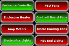
You can control any relay, by pressing any button on the screen. The buttons are push buttons, in order to change the background picture < .picc > from Arduino, only when the state of the relay is changed, so as to have a real feedback of the actual relay condition-state.
Also, a function was added to detect if Nextion is alive, by turning on a LED on pin 12. You could put a buzzer if you like to. In order to do that, a timer component was added on Nextion that sends an "alive message" to Arduino every 4,9 seconds in combination with a timer on Arduino, that has been set to 10 seconds, and if the "alive message" isn't received in 10 seconds or less, the pin 12 goes HIGH.
In addition, the page on Nextion refreshes every minute with the real state of the relays.
Much more, at the comments inside the code.
For more on how to learn to code with Nextion and Arduino, visit our Nextion Tutorial.
//                                   ______________________________________________
                                    //--------CREATED BY SEITANIS THANASIS--------\\
                                   //---------------VERSION 28/10/2019-------------\\
                                  //----------------- www.seithan.com --------------\\
                                 //----------------seithagta@gmail.com---------------\\
                                //---code for Power relays controlled with Nextion----\\

/*  Code for controlling Power Relays with Nextion and Arduino or other MCUs

 *  Copyright (C) 2019 author: THANASIS SEITANIS contact: seithagta@gmail.com
 *  This program is free software: you can redistribute it and/or modify
 *  it under the terms of the GNU General Public License as published by
 *  the Free Software Foundation, either version 3 of the License, or
 *  any later version.

 *  This program is distributed in the hope that it will be useful,
 *  but WITHOUT ANY WARRANTY; without even the implied warranty of
 *  MERCHANTABILITY or FITNESS FOR A PARTICULAR PURPOSE.  See the
 *  GNU General Public License for more details.
 *  You should have received a copy of the GNU General Public License
 *  along with this program.  If not, see <https://www.gnu.org/licenses/>.

 *  Not legally state for the distribution terms:
 *  It is permitted to copy and distribute native copies of the Program source code
 *  exactly as you have obtained it, on any storage medium, provided that:
 *  you will prominently and appropriately publish, in each copy, a copyright notice
 *  and a disclaimer of guarantee - that you will integrally include all notes mentioned
 *  in this License and in the absence of any warranty - and, finally, that you will provide
 *  each other recipient of the Program with a copy of this License together with the Program.
 *  You should make sure that the modified files provide prominent notes
 *  indicating the modification of the files and the date of modification.
 */
//------END OF COPYRIGHT NOTICE AND DISCLAIMER OF GUARANTEE------\\

/*
 * Τhe pins that every relay is connected to
 * 2 Enclosure_Controller 2
 * 3 Enclosure_Heater 3
 * 4 Amp_Meters 4
 * 5 Electronics_Lights 5
 * 6 PSU_Fans 6
 * 7 Control_Board_Fans 7
 * 8 Motor_Fans 8
 * 9 HotEnd_Lights 9
 * 12 pin output that comes HIGH when synq with Nextion lost can use it for led, buzzer etc
 */
/* define that Serial will de writed as "Nextion" (when we write Nextion.print the compiler reads Serial.print)
 *By defining the Nextion as Serial you can change at once the serial port at the whole code,
 * by changing the Serial to Serial1 for example
 */
#define Nextion Serial
#define REFRESH_TIME 60000 // time to refresh the Nextion page every 3 minutes
#define TIMEOUT_FOR_SYNQ 10000
  /* if this time is exceeded,
   * and Nextion doesn't send a confirmation message that it is alive,
   * the system will fall in safe mode and turn the relays off.
   */
boolean relay_state [8];  //An array with 8 places to store the Relays stage in booleans TRUE or FALSE
                          // LOW = false (relay off)    HIGH = true (relay on)

unsigned long timeout_synq = millis();
unsigned long refresh_timer = millis();  // timer for refreshing Nextion's page


void setup(){
  Nextion.begin(9600); // starting the serial port at 9600. NEXTION MUST HAVE THE SAME RATE. For this we write at
                       //  first page to the preinitialize event the command < baud=9600 >
                       // NOTE "bauds" will change the default baud rate off 9600 until it changed again

  for(int i = 0; i < 8; i++){
    relay_state[i] = false; //Setting the values of array relay_state to false (LOW)
    pinMode(i+2, OUTPUT); // Setting all pins as OUTPUT
    digitalWrite(i+2, LOW); //Setting all the relays to LOW (off)
  }

    pinMode(12,OUTPUT);
    digitalWrite(12,LOW);


  delay(500); //Waiting for Nextion to initialize

  /*reading the relay_state array and refreshing the Nextion page by sending the actual condition of the relays,
  * by sending < b(i).picc=0 > (the red picture) for those that are off (LOW) (false)
  * or by sending < b(i).picc=1 > (the green picture) for those that are on (HIGH) (true)
  * so as to have a feedback of the actual condition - state of the relays
  * because changing the color from Nextion, we do not ensure that the command has been excecuted from Arduino,
  * and we would see a fake green colored button (relay is on), without the relay being ON in real
  */
  for(int i = 0; i < 8; i++){
    if(relay_state[i] == false){
      Nextion.print("b");
      Nextion.print(i);
      Nextion.print(".picc=0");
    }else if(relay_state[i] == true){
      Nextion.print("b");
      Nextion.print(i);
      Nextion.print(".picc=1");
    }
    TFT_EndCommand(); // Sending the three bytes in order to terminate the instructions as Nextion needs < Nextion.print("\xFF\xFF\xFF"); >
  }
  timeout_synq = millis();
}


void loop(){
  if((millis()-refresh_timer) > REFRESH_TIME){
    Relay_control();
    refresh_timer = millis();
  }

  Nextion_serial_listen();
  check_Nextion_synq();
}


void Nextion_serial_listen()
{
/*
We are going to use the following Data Format:
<#> <len> <cmd> <Relay_button_number>
*        <#> declares that a command is followed
*        <len> declares the number of bytes that will follow (len = 2, <cmd> is the one Byte < Relay_button_number > is the other)
*        <cmd> declares the group of commands (R = Relay Control),you can add a different command group  later.
*        < Relay_button_number > is the Number of the button on Nextion (b0, b1...b7) that controls the relay
* From Nextion, at the release even of the button, we write: < printh 23 02 52 00 >, for b0
* For b1: < printh 23 02 52 01 > and so on...
*/

    if(Nextion.available() > 2){                 // Read if more then 2 bytes come (we always send more than 2 <#> <len> <cmd> <id>
        char start_char = Nextion.read();      // Create a local variable (start_char) read and store the first byte on it
        if(start_char == '#'){                // And when we find the character #
          uint8_t len = Nextion.read();      // Create local variable (len) / read and store the value of the second byte
                                            // <len> is the lenght (number of bytes following)
          uint8_t Relay_button_number;     // create variable to store the button number
          unsigned long tmr_1 = millis();
          boolean cmd_found = true;

          while(Nextion.available() < len){ // Waiting for all the bytes that we declare with <len> to arrive
            if((millis() - tmr_1) > 100){    // Waiting... But not forever......
              cmd_found = false;              // tmr_1 a timer to avoid the stack in the while loop if there is not any bytes on Serial
              break;
            }
            delay(1);                           // Delay for nothing delete it if you want
          }

            if(cmd_found == true){            // So..., A command is found (bytes in Serial buffer egual more than len)
              uint8_t cmd = Nextion.read();  // Create local variable (cmd). Read and store the next byte. This is the command group

              switch (cmd){

               case 'R':
                        /* or <case 0x52:>  IF 'R' matches, we have the command group "Relay control".
                        * The next byte  according to our protocol is the value for the <Relay_button_number>
                        */
                  Relay_button_number = Nextion.read();  // we read and store the byte at the variable

                  if(relay_state[Relay_button_number] == false){
                    relay_state[Relay_button_number] = true;

                  }else if(relay_state[Relay_button_number] == true){
                    relay_state[Relay_button_number] = false;
                  }
                  timeout_synq = millis(); // setting the timer to be equal to millis(), because Nextion sent a alive message
                  Relay_control();
                  break;

                    case 'S':
                   /* or <case 0x53:>  if 'S' matches, we have the command group "Nextion is Synchronized".
                    * From the timer component on Nextion, we send every 4,9 seconds a < printh > command
                    * so we check if Nextion is connected and synchronized.
                    * If it is not, pin 12 turns HIGH as Alarm
                    * We check the above, by writing in the timer's event: < printh 23 01 53 >
                    */
                  timeout_synq = millis(); // setting the timer to be equal to millis(), because Nextion sent a alive message


                  break;


              }
            }
        }
    }
}

void Relay_control()
{
  /*reading the relay_state array and refreshing the Nextion page by sending the actual condition of the relays,
  * by sending < b(i).picc=0 > (the red picture) for those that are off (LOW) (false)
  * or by sending < b(i).picc=1 > (the green picture) for those that are on (HIGH) (true)
  * so as to have a feedback of the actual condition - state of the relays
  * because changing the color from Nextion, we do not ensure that the command has been excecuted from Arduino,
  * and we would see a fake green colored button (relay is on), without the relay being ON in real.
  * We also added the digitalWrite , in order to turn OFF or ON the relays.
  * The button b0 is stored at 0 place of array relay_state[0] , but the pins start from 2.
  * That is why we add +2 at digitalWrite command.
  */
  for(int i = 0; i < 8; i++){
    if(relay_state[i] == false){
      digitalWrite(i+2, LOW);
      Nextion.print("b");
      Nextion.print(i);
      Nextion.print(".picc=0");
    }else if(relay_state[i] == true){
      digitalWrite(i+2, HIGH);
      Nextion.print("b");
      Nextion.print(i);
      Nextion.print(".picc=1");
    }
    TFT_EndCommand(); // Sending the three bytes in order to terminate the instructions as Nextion needs < Nextion.print("\xFF\xFF\xFF"); >
    delay(1); //just to give Nextion some time to read the Serial (it is not necessary)
  }

}

void check_Nextion_synq()
{
 if((millis() - timeout_synq) > TIMEOUT_FOR_SYNQ ) {
     digitalWrite(12,HIGH);
     /* you could put a buzzer here (pin 12) to notify you that the connection is lost
      * for the LED, you will need a 220ohm in series.
      * Here we turn the buzzer or the LED on
      */
    }else{
    digitalWrite(12,LOW); //stops the LED or the buzzer if synq comes back
    }
}

void TFT_EndCommand()
{
  // Sending the three bytes in order to terminate the instructions as Nextion needs < Nextion.print("\xFF\xFF\xFF"); >
  Nextion.print("\xFF\xFF\xFF");
}
The .zip file contains a .HMI file for Nextion and a .ino file for Arduino
File downloaded
2305 times.